At cryogenic temperatures, even small thermal resistances can have a significant impact on system performance. When the goal is to cool a superconducting component to 4 Kelvin, every layer of material and every mechanical interface in the thermal path must be designed for maximum conductivity. That is why thermal contact engineering is one of the most critical elements of coldmass design.
In this post, we will explore how Re:Build DAPR analyzes thermal resistance across materials and joints, and how we optimize stack-ups, fasteners, and thermal interface materials to ensure rapid and reliable heat transfer at cryogenic temperatures.

Cooling a system from room temperature to 4 Kelvin is not as simple as turning on the helium. Heat must flow efficiently from the source to the cold head, through multiple layers of materials, adhesives, and mechanical connections. Any resistance along the way can become a bottleneck that slows cooldown or leads to uneven temperatures.
In cryogenic environments, where active cooling power is limited and temperature gradients are narrow, thermal design must account for:
Even when materials like aluminum or copper are used, poor contact conductance at joints can drastically reduce the overall effectiveness of the thermal path.
In one recent project, Re:Build DAPR was tasked with keeping a superconducting coil cold within a complex layered structure. The cooling component was bolted to an aluminum bobbin, which was epoxied to the coil. This created two primary thermal paths in parallel: one through the left side of the coil and one through the bottom.
To model the system, we analyzed the resistivity across the full stack-up, considering each material’s thickness, conductivity, and surface area. We applied parallel path formulas to calculate the net resistance and used simplified 1D and 2D models to identify bottlenecks in the heat flow.
Key formulas used in our calculations include:
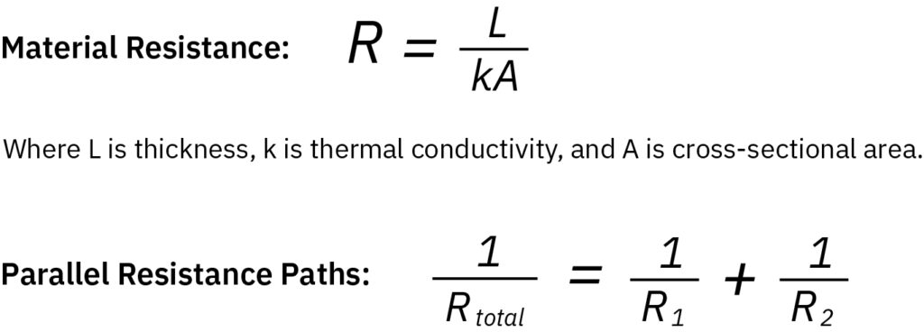
These models allowed us to optimize the thermal performance of each path and guide design decisions about joint configurations and material selection.
One of the biggest challenges in cryogenic thermal design is modeling the conductance of bolted joints. Unlike a welded connection, a bolted joint does not provide full contact across the interface. Instead, contact occurs only at microscopic asperities, and the actual area of conduction depends heavily on:
In a cryogenic vacuum, where there is no conduction through trapped gases and no significant thermal radiation, the only remaining mode of heat transfer at the interface is solid-to-solid conduction. This makes accurate modeling of the joint essential.
Re:Build DAPR uses a pressure cone method to estimate the contact area under a bolt head and calculates clamp pressure using torque, bolt diameter, and torque coefficients. This data feeds into thermal models that predict joint conductance based on pressure, material stiffness, and surface roughness.
Because no mechanical joint is perfectly flat, it is often necessary to use thermal interface materials (TIMs) to improve conductivity across bolted or clamped connections. Common options include:
The choice of TIM depends on the specific design, required conductance, and ease of assembly. Re:Build DAPR selects and tests TIMs based on the material pairing, pressure levels, and surface conditions at the joint.
At 4 Kelvin, small inefficiencies become big problems. That is why Re:Build DAPR brings advanced modeling, practical experience, and precision testing to every thermal contact challenge. Whether we are optimizing stack-ups, selecting interface materials, or modeling preload-dependent joint conductance, we design every thermal path to perform under the harshest cryogenic conditions.
Want to know more about how Re:Build DAPR engineers coldmass systems to perform at 4K? Stay tuned for Blog 3 in the series: Holding It Together: Maintaining Bolt Preload with Belleville and Thermal Washers.
Looking to connect with an experienced team?
Look no further than Re:Build Optimation! We are excited to connect with you.